Scan-to-BIM Workflow Explained: From LiDAR Point Cloud to BIM Model
The scan to BIM workflow is now the most reliable method for creating accurate BIM models from existing buildings and construction sites. It replaces manual measured surveys with LiDAR-captured point clouds. The result is a faster, more complete, and spatially verified input to Revit, Navisworks, and IFC-based design environments. This article explains every step taken from field capture to final model. The explanation includes file formats, LOD expectations, and which building elements can LiDAR captures well.
What Is the Scan to BIM Workflow?
Scan to BIM is the process of converting a physical building or site into a parametric BIM model. It starts with a LiDAR scan. The scan produces a point cloud (a dense collection of millions of georeferenced 3D points). A BIM modeller then uses that point cloud as a reference to build accurate geometry inside BIM software such as Revit or a similar platform.
In contrast to traditional measured surveys, LiDAR captures the full geometry of a space simultaneously. Therefore, every wall, column, beam, and floor surface is recorded in a single pass. Manual surveys, however, only record the points a surveyor chooses to measure.
Where Scan to BIM Fits in a Project
The scan to BIM workflow applies to two main scenarios. First, it serves existing building documentation, where no accurate record model exists and one is needed for renovation, refurbishment, or heritage recording. Second, it supports construction verification, where a BIM model exists and the team needs to confirm the building was constructed as designed.
In both cases, the workflow starts with a LiDAR scan and ends with a verified, georeferenced BIM model. Furthermore, the same point cloud can support multiple deliverables simultaneously. The example of derivelable such as: Revit model, clash detection, and 2D drawing extraction all from one dataset.
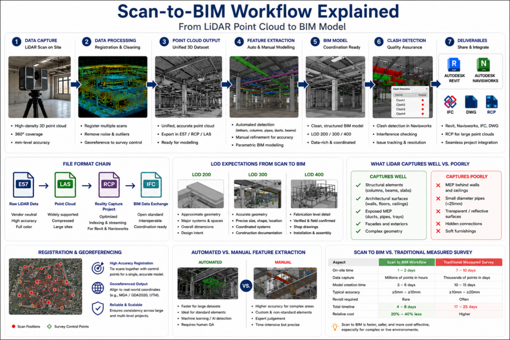
The Scan to BIM Workflow
The complete scan to BIM workflow follows a consistent sequence of steps. Each step depends on the previous one. Consequently, errors introduced early, for example in registration, propagate through to the final BIM model.
The File Format Chain — E57, LAS, RCP, and IFC Explained
File format compatibility is one of the most common pain points in the scan to BIM workflow. Understanding what each format does prevents delays and rework at the handover stage.
| Format | Stage | Used In | Notes |
|---|---|---|---|
| E57 | Raw capture / registration | Leica Cyclone, Faro Scene, ReCap | Open standard; preserves full point density and intensity data |
| LAS / LAZ | Raw capture / processing | CloudCompare, ReCap, ArcGIS | Standard for LiDAR data; LAZ is compressed version |
| RCP / RCS | BIM import | Autodesk Revit, AutoCAD | Autodesk’s indexed format; RCP links to multiple RCS files |
| IFC | BIM model export | All major BIM platforms | Open standard for model exchange; not a point cloud format |
| NWD / NWC | Clash detection | Autodesk Navisworks | Combines point cloud and BIM geometry for clash review |
| PTX / PTG | Static scanner output | Leica Cyclone | Proprietary formats; convert to E57 for wider compatibility |
The Recommended Format Chain for Revit Projects
For most Revit-based scan to BIM projects, the recommended format chain is straightforward. Start with E57 or LAS from the scanner. Process and register in Autodesk ReCap. Export as RCP for Revit import. Model in RVT. Finally, export to IFC for consultant sharing or NWD for Navisworks clash detection.
Important: Revit does not import E57 or LAS directly. Always convert to RCP via Autodesk ReCap first. Skipping this step is the most common cause of format compatibility failures in scan to BIM projects.
Point Cloud Registration and Georeferencing
Registration and georeferencing are two separate steps. Both are critical. Confusion between them causes positional errors that are difficult to detect until the BIM model is complete.
Registration
Registration aligns multiple scan positions into a single unified point cloud. The scanner captures data from many positions across the site. Each position is a separate file. Registration software, such as Leica Cyclone or Faro Scene, matches overlapping geometry between adjacent positions.
Two registration methods exist. Target-based registration uses physical survey targets placed around the site before scanning. Cloud-to-cloud registration matches geometry automatically without targets. In practice, target-based registration is more accurate. Cloud-to-cloud is faster for large open sites with abundant geometry.
Georeferencing
Georeferencing ties the registered point cloud to a real-world coordinate system. In Australia, this means MGA2020 (Map Grid of Australia 2020). A licensed surveyor establishes control points on site using GNSS equipment. These control points are then matched to known positions in the point cloud.
Moreover, georeferencing ensures the BIM model aligns with site boundaries, adjoining buildings, and infrastructure. Without it, the model exists in an arbitrary coordinate space. Consequently, it cannot be used for town planning, council submission, or infrastructure coordination.
LOD Expectations: What LiDAR Delivers at LOD 200, 300, and 400
Level of Development (LOD) defines how much geometric and non-geometric information a BIM element contains. The scan to BIM workflow can deliver LOD 200 through to LOD 400. But the achievable LOD depends on what the scanner can physically see.
| LOD Level | Description | Typical Application | Achievable from LiDAR? |
|---|---|---|---|
| LOD 200 | Approximate geometry, size, shape, location, and orientation | Concept design, spatial planning, heritage documentation | ✅ Yes — readily achievable |
| LOD 300 | Precise geometry with accurate size, shape, location, and orientation | Construction coordination, as-built documentation, clash detection | ✅ Yes — standard deliverable for most projects |
| LOD 400 | Full fabrication-level detail including connections and fixings | Structural steel, prefab, and specialist trade coordination | ⚠️ Partial — visible elements only; hidden fixings require supplementary data |
LOD 300 is the most common deliverable for scan to BIM projects. It captures accurate floor-to-floor heights, wall thicknesses, structural grid positions, and opening locations. Furthermore, LOD 300 is sufficient for clash detection, renovation design, and most as-built BIM requirements.
LOD 400 is achievable for exposed structural elements. For example, visible steel connections in an industrial building. However, embedded fixings, post-tensioning tendons, and connections hidden within concrete cannot be captured by LiDAR. Therefore, supplementary drawings or destructive investigation are required for those elements.
Automated Versus Manual Feature Extraction in Scan to BIM
Feature extraction is the process of converting a raw point cloud into modelled BIM elements. Two approaches exist including automated and manual. In reality, most real-world projects use a combination of both.
Automated Extraction
Automated extraction software analyses the point cloud and identifies geometric patterns. It then generates BIM elements automatically. Tools such as Autodesk ReCap Photo, Leica BLK360 workflows, and third-party plugins like Scan-to-BIM (Autodesk App Store) can extract flat surfaces, cylinders, and regular geometry with reasonable accuracy.
Automated extraction works well for simple and regular geometry. For example, flat walls, floor slabs, and cylindrical columns are reliable candidates. As a result, automated tools can accelerate LOD 200 and basic LOD 300 modelling significantly.
Manual Extraction
Manual extraction involves a BIM modeller tracing geometry directly from the point cloud inside Revit or a similar platform. This approach is slower. However, it produces more accurate results for complex geometry such as curved surfaces, non-orthogonal walls, and irregular structural members.
In addition, manual extraction is necessary wherever automated tools fail. Automated tools mostly fail to extract complex geometry. Consequently, most professional scan to BIM workflows use automated tools to accelerate repetitive elements and manual modelling to handle exceptions.
What LiDAR Captures Well and Where It Struggles
Understanding LiDAR’s limitations is as important as understanding its strengths. A well-managed scan to BIM workflow plans around these limitations at the capture stage so we can prepare the best workflow for each condition.
✅ LiDAR captures well
- Exposed structural concrete and steel surfaces
- Floor slabs, ceilings, and wall faces
- Stair geometry, ramps, and inclined surfaces
- Facade and exterior cladding profiles
- Large mechanical plant (exposed AHUs, chillers)
- Visible pipe runs and ductwork in open ceiling spaces
- Column and beam positions and cross-sections
- Window and door opening locations and sizes
⚠️ LiDAR struggles with
- MEP services concealed behind walls or above closed ceilings
- Embedded structural connections and post-tensioning
- Transparent surfaces such as glass reflects or passes laser pulses
- Highly reflective surfaces such as mirrors, polished metal
- Very dark or light-absorbing materials (low return intensity)
- Underground services not accessible during scanning
- Fine pipe diameters under approximately 20 mm
- Elements behind temporary hoarding or formwork
Knowing these constraints in advance allows the project team to plan supplementary data collection. For example, MEP services above a closed ceiling may require intrusive investigation or design drawings as the source of truth.
Scan to BIM vs Traditional Measured Survey: Cost and Time Comparison
This comparison is rarely published in detail by scan to BIM providers. However, it is the first question most project managers ask. The following figures reflect a typical 10-storey commercial office building of approximately 15,000 m² GFA in an Australian capital city.
Cost and Time Comparison — 15,000 m² Commercial Building
- On-site survey: 8–12 days (2-person team)
- CAD/BIM modelling from notes: 15–25 days
- Total elapsed time: 5–8 weeks
- Estimated cost: $45,000 – $80,000 AUD
- Coverage: measured points only — gaps common
- Accuracy: dependent on surveyor judgment
- Revisit risk: high — missed elements require return visits
- On-site scanning: 1–2 days
- Registration and processing: 1–2 days
- BIM modelling to LOD 300: 8–15 days
- Total elapsed time: 2–4 weeks
- Estimated cost: $18,000 – $40,000 AUD
- Coverage: full surface capture — no gaps
- Accuracy: ±10 mm verified against point cloud
- Revisit risk: low — point cloud is permanent reference
Note: Costs and timeframes are indicative only and vary with building complexity, access conditions, and LOD requirements. Contact GeoAI for a project-specific quote.
The time saving is most significant during on-site capture. In contrast, BIM modelling time is reduced but not eliminated. A human modeller is still required for LOD 300 and above. Moreover, the point cloud remains available as a permanent reference after the model is delivered. Consequently, any future query about building geometry can be checked against the original scan data without returning to site.
Clash Detection Using Scan-to-BIM Data in Navisworks
One of the highest-value applications of the scan to BIM workflow is clash detection between the as-built condition and new design elements. This is especially relevant for building services upgrades, fitout projects, and structural modifications in existing buildings.
How Clash Detection Works with Point Cloud Data
Navisworks accepts both point cloud data (in NWC format) and BIM model geometry simultaneously. The clash detection engine compares the two datasets and flags intersections. As a result, a proposed new duct run that conflicts with an existing beam can be caught before fabrication.
Furthermore, Navisworks can run hard clash, clearance clash, and duplicates detection against point cloud geometry. Hard clashes identify physical intersections. Clearance clashes flag elements that are too close for maintenance access. Both use cases are directly supported by LiDAR-sourced data.
Common clash detection scenarios using scan-to-BIM data
- New services route conflicts with existing structural beams not on original drawings
- Proposed partition walls intersecting existing ceiling-mounted fire services
- New mechanical plant clearance conflicts with adjacent existing plant
- Facade upgrade elements clashing with existing window frame positions
- Base building services conflicts with tenant fitout design in commercial refurbishment
Need Scan-to-BIM Delivery in Australia?
GeoAI provides end-to-end scan-to-BIM services across Sydney and Australia. Our team handles LiDAR capture, point cloud registration, georeferencing, and BIM modelling — from LOD 200 through to LOD 400. Talk to our team about your project requirements.
Discuss Your Scan-to-BIM Project →Frequently Asked Questions
What is the difference between a point cloud and a BIM model?
A point cloud is a raw collection of millions of 3D measurement points captured by a LiDAR scanner. It represents physical reality accurately but contains no intelligence such as no walls, no floors, no object properties. A BIM model, in contrast, is a structured parametric model built by a modeller using the point cloud as a reference. The BIM model contains named elements, material properties, and relationships between objects. Therefore, the point cloud is the source data and the BIM model is the deliverable.
Can I load a point cloud directly into Revit?
Not directly from E57 or LAS format. Revit requires point clouds in Autodesk’s RCP format. You must first process the raw scan files through Autodesk ReCap, which indexes the data and generates the RCP file. Once in RCP format, the point cloud loads into Revit and can be used as a modelling reference. Furthermore, ReCap allows you to crop, clean, and organise the point cloud before import.
What LOD should I specify for a commercial refurbishment project?
LOD 300 is the standard specification for commercial refurbishment scan-to-BIM projects. It provides accurate geometry for all visible building elements such as walls, floors, ceilings, columns, beams, and major openings. This is sufficient for services coordination, partition layout design, and clash detection against new design elements. LOD 400 is only necessary if you require fabrication-level detail for specific elements such as exposed structural steel connections. In most cases, specifying LOD 400 across the whole building increases cost significantly without proportional benefit.
How accurate does the point cloud need to be for BIM modelling?
For LOD 300 BIM modelling, a registered point cloud accurate to ±6 mm is sufficient. GeoAI’s mobile LiDAR achieves ±10 mm or better under typical site conditions. Moreover, the modeller introduces additional tolerance during the BIM authoring process. Consequently, the final LOD 300 model typically carries a combined tolerance of ±15 to ±20 mm against the physical building. This result is within acceptable limits for the vast majority of renovation and documentation projects.
Does GeoAI deliver scan-to-BIM services outside Sydney?
Yes. GeoAI provides LiDAR scanning and scan-to-BIM services across Australia. Sydney is our primary service area, and we cover the full Sydney metropolitan region and Greater Sydney. For projects in Melbourne, Brisbane, Perth, Adelaide, and regional locations, our team can mobilise with appropriate notice. Contact us directly to confirm availability and pricing for projects outside New South Wales.
Related GeoAI Services
For verified as-built documentation at practical completion, see our As-Built Drawing Survey Sydney service. For ongoing site verification throughout the construction programme, visit our Construction Digital Twin Sydney page. For further reading on BIM standards and LOD definitions, the buildingSMART International LOD framework is the authoritative global reference.
Category List
- 3D Point Cloud
- Artificial Intelligence
- Asset Management
- Digital Twin
- Featured
- Hardware
- Knowledge Graph
- LiDAR
- News
- Site Monitoring
- Vegetation Monitoring
- Virtual Reality
Recent Post
- What Is GIS-Ready Data? How LiDAR Outputs Feed Into Spatial Systems
- Scan-to-BIM Workflow Explained: From LiDAR Point Cloud to BIM Model
- As-Built Drawing Survey Sydney: LiDAR Verification for Construction Projects
- Digital Twin for Construction Projects – How LiDAR Powers Real-Time Site Models
- Road Asset Management Sydney